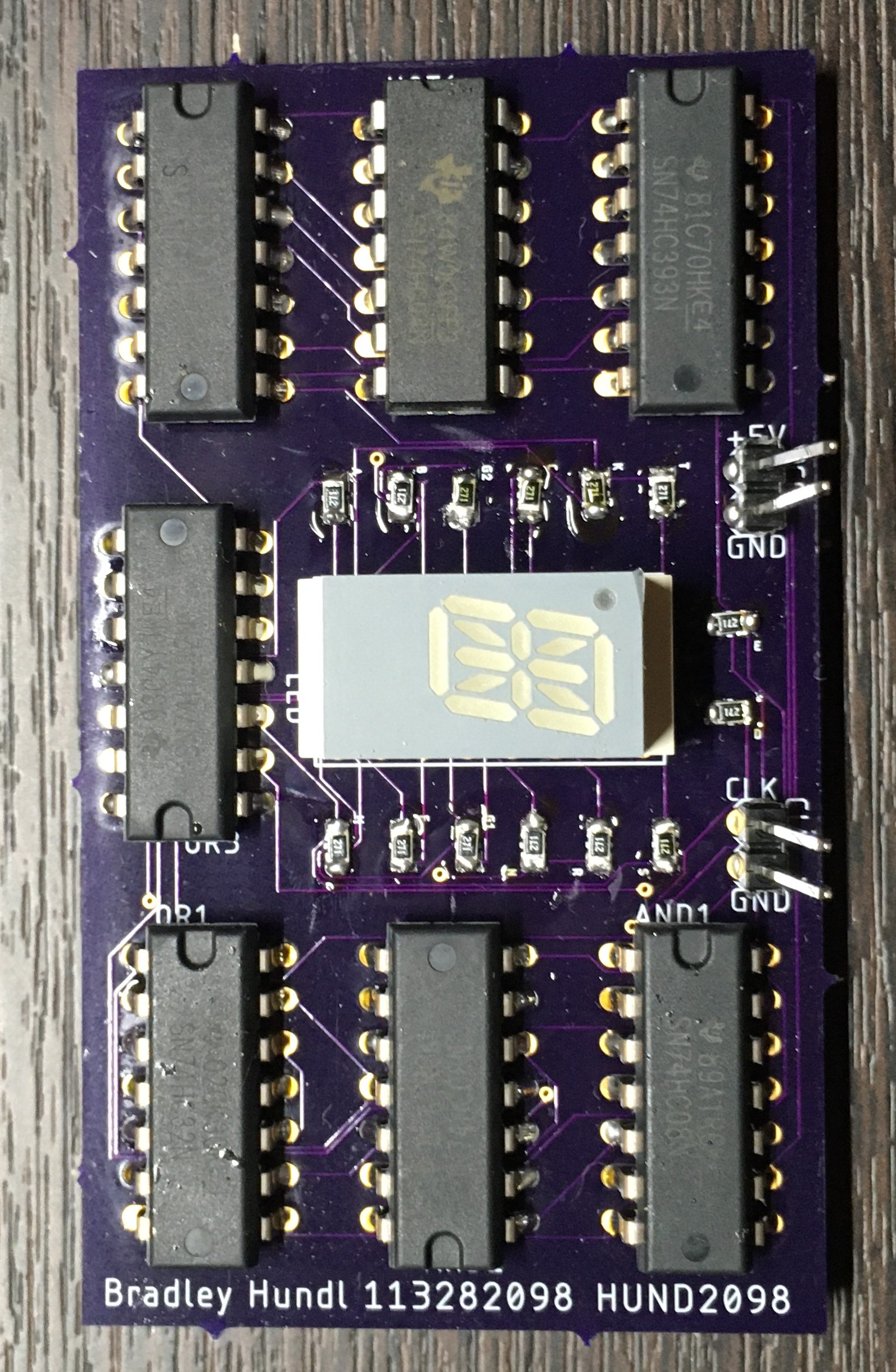
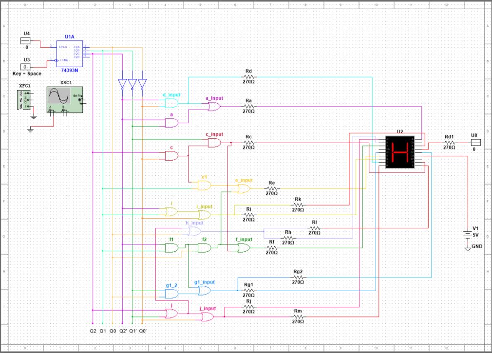
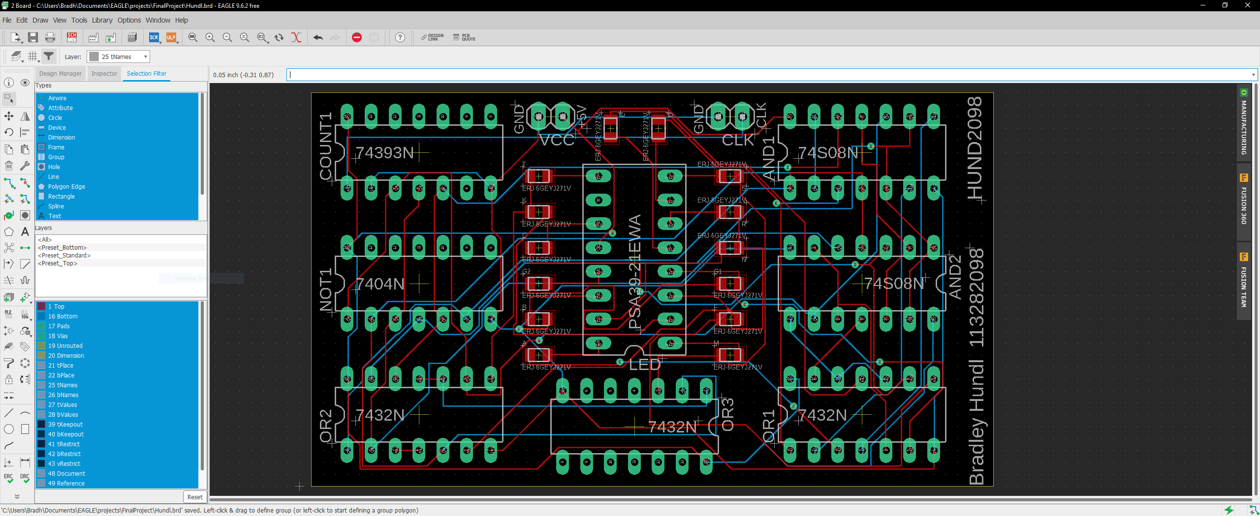
In this project, I needed to design a PCB which would display my student 4x4 (HUND2098), at the University of Oklahoma on a continuous loop while hooked up to a signal generator. I began the process by working with pen and paper to derive the boolean logic necessary and simplify it using Kmaps. Once I had the logic, I was able to use Multisim software where I created the schematic using logic gates and other components to go on the PCB. I then tested my schematic using Multisim's simulation feature. Once I had a working schematic I brought it over to the EAGLE PCB Design software and began to design the actual board itself. Once I had my PCB file I uploaded it to oshpark.com where they manufactured it in Seattle, WA. Upon receiving the board, I soldered all of the components by hand and tested it using a power supply and a signal generator at a low frequency. As seen in the video below, my board worked exactly to specifications.


